Author: Roland Kuit
If you like to play with these patches, you will need the Clavia NMG2 Demo
version. You can find it here:
Clicking the pictures will download the
patches into the NMG2 Demo.
For Mac users
please go
here to download OSX compatible NMG2Demo sotware:
Shepard tone, named after Roger Shepard, is a sound
consisting of a superposition of sine waves separated by octaves. When played
with the base pitch of the tone moving upward or downward, it is referred to as
the Shepard scale. This creates the auditory illusion of a tone that continually
ascends or descends in pitch, yet which ultimately seems to get no higher or
lower. It has been described as a "sonic barber's pole". The acoustical illusion
can be constructed by creating a series of overlapping ascending or descending
scales.
Boolean logic, originally developed by George Boole in the mid
1800s, allows quite a few unexpected things to be mapped into bits and bytes.
The great thing about Boolean logic is that, Boolean logic is very simple.
Logic Gates: NOT, AND, OR. And combinations with these three to create: XOR,
NAND, NOR and XNOR. With these simple gates you can build combinations that
will implement any digital component you can imagine. In modular synthesis we
are used to logic as a trigger function. Simple ON/OFF circuits out of
sequencers triggering envelope generators etc. In my eBooks I explain how to
build very complicated sequencers. The patch we will discuss below is quite
simple and we will apply logic in an other way. The other side of logic, so to
speak. In this lecture you will learn how to build an oscillator, LFO etc.
in order to create a sound producing device! As you might know, an
oscillator is a device switching from the highest amplitude to the lowest.
Repeatedly. A logic inverter that switches positive to negative and vice versa.
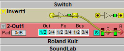
The simplest possible gate is called an "inverter," or a NOT gate. It takes one
bit as input and produces as output its opposite. The truth table below shows a
logic table for the NOT gate. Symbolized as follows in circuit diagrams with "Q"
as output:
A Q 0 1 1 0
Connecting the output to the input
we create a loop. It produces sound. Audio on a 96kHz rate. The frequency is a
bit high to work with so we have to find a way how to tune it.
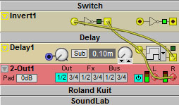
A Logic Divider module is practical however it is a little
static and of no use for our purpose. As we want to create an
oscillator whereby we can modulate its pitch. Using a Logic Delay module
offers us the opportunity to tune the audio
frequency in a controlled way:
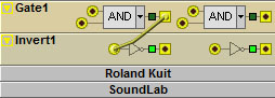
The Inverter module is switching from 0 to 1 in a loop with the Delay module. Increasing the delay by turning the knob will cause a slower loop and therefore a lower frequency.
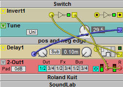
A more elegant way is to use a Constant
(''Tune'') module:
We can use the the Sub/Low/High button,
but we don't. We use the Delay Type drop-down selector instead. Select Delay Type
between Positive Edge Delay (only the positive edge of the input signal is
delayed), Negative Edge Delay (only the negative edge of the input signal is
delayed) and Cycle Delay (the entire input signal cycle is delayed). We
have created a autonomous logic oscillator with a modulation input.* The Constant
module is modulating the frequency. Next step: Creating a
LFO with a ramp wave. Before we can create this we will have to
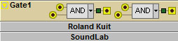
understand some other logic gates. The AND gate:
A B Q 0 0 0 If A is 0 AND B is 0, Q is 0 0 1 0 If A is 0 AND B is 1, Q is 0 1 0 0 If A is 1 AND B is 0, Q is 0 1 1 1 If A is 1 AND B is 1, Q is 1
The AND operation says if and only if all inputs are on, the output will be on.
To show you a NAND gate we need combinational logic. The logic ladder form
would be an AND gate, followed by a NOT gate:
The logic truth table for this would be:
A
B
Q 1 1 0 1 0
1 0 1 1 0 0 1
As a patch:
When we use the drop-down selector we can choose the NAND gate directly.
A combination of NAND gates can form a Flip-Flop module.
The flip-flop is a circuit that has two stable states and can be used to store state
information. The circuit can be made to change state by signals applied to
one or more control inputs and will have one or two outputs. It is the basic
storage element in sequential logic constructed with three NAND gates** :
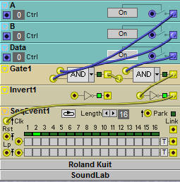
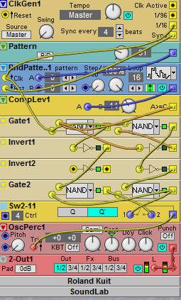
A Clock Generator triggers a Pattern Generator. The Compare Level module
generates a trigger signal as data signal triggering a Percussion oscillator.
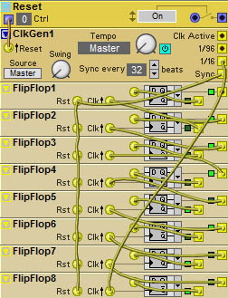
We need this Flip-flop device to create a BinCounter module. That is a digital
circuit which has a clock input and a number of count outputs which give the
number of clock cycles. A sequential row of Flip-flops can form a Binary
Counter.
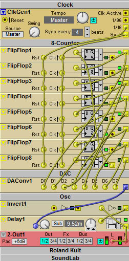
The 8-Bit Ring Counter:
As a modulation source for an oscillator by a DAConverter module:
We can follow the trigger decay in a sequence through all Flip-flop modules.
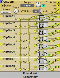
Creating a BinCounter****:
8 Flip-Flop modules whereby the Q2 output is the input for each Flip-flop
own D=input.
Q1 acts as trigger for the previous Flip-flop:
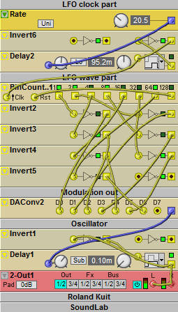
Constructing our LFO module**:
The delayed Logic Inverter loop is triggering the Binary Counter module as a Clock
Generator. Output 8 is
resetting the module. The outputs are
inverted in such way to get a ramp up wave. The Digital to Analogue
Converter module transforms the
logic input into an analogue modulation signal. A pitch modulating LFO wave for the Logic Delay module which is
in a loop with the Logic Inverter to create an autonomous logic oscillator.
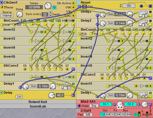
All we need to do is to copy the LFO block with oscillator. We delay the
trigger to the second oscillator by a Logic Delay module to create a phase difference. Pushing the reset button
will restart both BinCounters. The second BinCounter restarts in an other phase
created by a Logic Delay module. To minimize the output of the LFO, we leave out the D0
and D7 input of the
DAConverter.
Two phase:
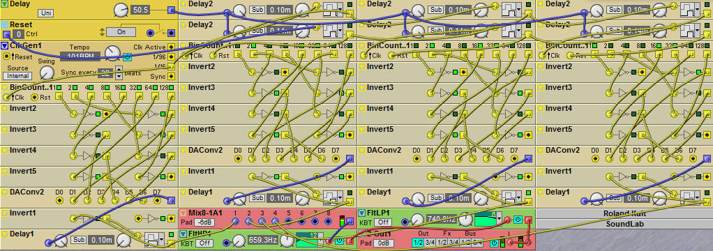
Extending the patch above results in a four phase Barber's pole:
The Boolean Barber's pole**
Push the Reset-Button in order to get the right phase. Additional we
apply a High- and Low Pass
serial
filter circuit to smooth the output.
Summarizing we created the following
logic devices: Oscillators, LFO's, Flip-Flops, BinCounters and applied trigger and
reset phase delays.
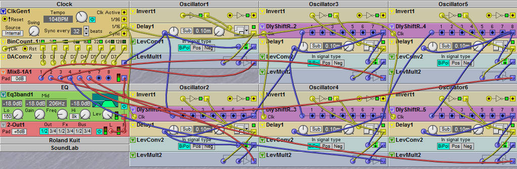
A more elegant way to create a digital
Barber's Pole is to make use of Shift Register modules. A shift register is a
cascade of flip flops, sharing the same clock, in which the output of each
flip-flop is connected to the "data" input of the next flip-flop in the chain,
resulting in a circuit that shifts by one position the "bit array" stored in it,
shifting in the data present at its input and shifting out the
last bit in the array, at each transition of the clock input. More generally, a
shift register may be multidimensional, such that its "data in" and stage
outputs are themselves bit arrays: this is implemented simply by running several
shift registers of the same bit-length in parallel.** The
phase difference is created with Shift Register modules: control data delays of
the LFO's modulation wave output. Without the inverters the LFO's output
causes a downward modulation signal.
A six phase Boolean Barber's
Pole**
This is just one example. Understanding Boolean logic provides many new
possibilities to design today's sound.
Roland Kuit This little lecture designed to use with your internet browser (screen
width 1243). Start with installing the NMG2
Demo software, located in the file Clavia software for
PC/Mac (Leopard user have
to install VMWare, or Parallels and a Windows version).For
OSX Lion: Step 1 Download and install
WineBottler. Step 2 – Install.
Once installed WineBottler, go where you saved G2 Demo installer, unzip it and
double click“ SetupModularG2Demo_V140.exe”. A window will pop up asking what to
do with that file. Select “Convert to simple OSX application” and click OK. In
the next window, scroll down Winetricks list and check “winxp” option, then
click INSTALL. On “Save As” dialog window, name your application as “Nord
Modular G2 Demo”, select “Applications” as target folder and click SAVE. Now
WineBottler will start to install the software and a new window will pop up with
the old beloved windows installer. Go on with installation and, when a window
with a directory tree will show just close it and complete G2 Demo installation
following screen instructions. Now WineBottler will ask you which file should be
started. Select “Modular G2 Demo v1.40.exe” from the list and click OK. Now you
will find your packed software under “Applications” in your Finder.
Unfortunately, seems that this software won’t work as packed wine application so
you will need to do a further step. Go in your “Applications” folder and delete
the app you just created (Nord Modular G2 Demo), then go to: /your_user/Library/Application
Support/Wine/prefixes. Here you will find a folder named “Nord Modular G2 Demo”
with all installed files under: drive_c/Clavia/Modular G2 Demo v1.40. From there
just drag the executable file to your “Applications” folder holding CMD+OPTION
to create a link and rename it as “Nord Modular G2 Demo”. Open the NMG2Demo and click the dropdown menu Setup. Select the
appropriate soundcard and put the sample rate at 96000.